Bending Stress and "Inertia" Calculations in 2 Minutes! YouTube

Relation between the radius of curvature, R, beam curvature, κ , and the strains within a beam subjected to a bending moment. The bending moment can thus be expressed as. M = ∫y(EκydA) = κE∫y2dA. This can be presented more compactly by defining I (the second moment of area , or " moment of inertia") as. I = ∫y max 0 y2dA.
Shear Force and Bending Moment Diagram Calculator

Online Calculator: Bending Moments. The bending moments calculator allows you to position one or two supports and up to six point loads along a straight beam and calculate the bending moments at any of the forces or supports entered. Go to the bottom of the page for help with its use. Enter beam length:
How to Calculate Bending Moment Diagram? SkyCiv
When transverse force is applied on a section of beam, the stresses produced will be known as bending stresses. Consequently, applied forces cause the bending moment which is commonly quantified as force x distance (kN-m). While measuring the bending, the force must be perpendicular to the moment arm.
Max Bending Moment equations YouTube

Step 4: Sum Up All Calculated Moments. To find the total bending moment at the specific point on your structure, sum up all individual moments calculated in step 3. Total Bending Moment (MT) = Σ Moment_i. Remember to maintain the correct signs (+/-) for all moments during these calculations. Step 5: Analyze the Results.
Maximum Bending Moment for BENDING stress in Under 3 Minutes! YouTube

Loads. Calculation. Beam Length L,(m): Length Unit: Force Unit: Go to the Supports. Section Parameters. 10 (m) Calculate the reactions at the supports of a beam - statically determinate and statically indeterminate, automatically plot the Bending Moment, Shear Force and Axial Force Diagrams.
Bending Moments

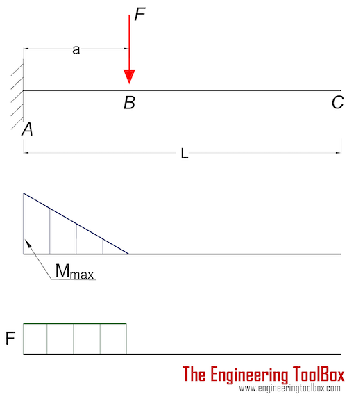
Plots of V(x) and M(x) are known as shear and bending moment diagrams, and it is necessary to obtain them before the stresses can be determined. For the end-loaded cantilever, the diagrams shown in Figure 3 are obvious from Eqns. 4.1.1 and 4.1.2. Figure 4: Wall reactions for the cantilevered beam.
Uniformly Distributed Load (UDL) Shear Force and Bending Moment Diagram [SFD BMD Problem 4

the first beam max stress varies along with the height of the section in an inverse triangle starting from zero at the base (small-angle: no strain due to pin-pin support) and ends up on the top face as σmax σ m a x. so the total stress triangle area is. Astress = bσm ∗ h 2 Mmax = bh 2 σmax ∗ 2h 3momentarm Mmax = bh2σmax 3 A s t r e s.
How to Calculate Bending Moment Diagram? SkyCiv
Bending moment and Shearing force are very important factors to be considered for design of any structural . component.. Bending moment at a section of a structural element is defined as the reaction developed in a structural element when an external force or moment is applied to the element that causes the element to be bent.. Bending moment at a section of beam is calculated as the algebraic.
Shear force & Bending Moment Formulas With Diagram CCAL Shear force, Bending moment, Civil

To find the bending stress of a square beam, you can use the following equation: σ = 6 × M / a³. Say a square beam has a side measurement, a, of 0.10 m and experiences a 200 N·m bending moment. Substituting these values into our square beam bending stress equation, we get: σ = 6 × M / a³. σ = 6 × 200 N⋅m / (0.10 m)³.
Exercise Shear Force & Bending Moment Diagrams TU Delft OCW
Mathematically, bending moment is the algebraic sum of the moments applied to the beam at any point along its length. It is calculated by multiplying the force acting on the beam by the distance from the beam's end to the point at which the bending moment is required. Bending moments can be positive or negative depending on the specific.
How to Calculate Bending Moment Diagram? SkyCiv
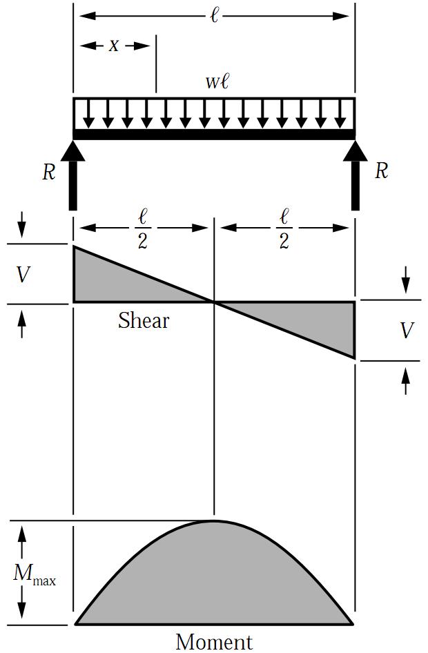
Shear and moment diagram for a simply supported beam with a concentrated load at mid-span.. In solid mechanics, a bending moment is the reaction induced in a structural element when an external force or moment is applied to the element, causing the element to bend. The most common or simplest structural element subjected to bending moments is the beam.The diagram shows a beam which is simply.
Bending Moment Equation For Cantilever Beam With Udl Diy Projects
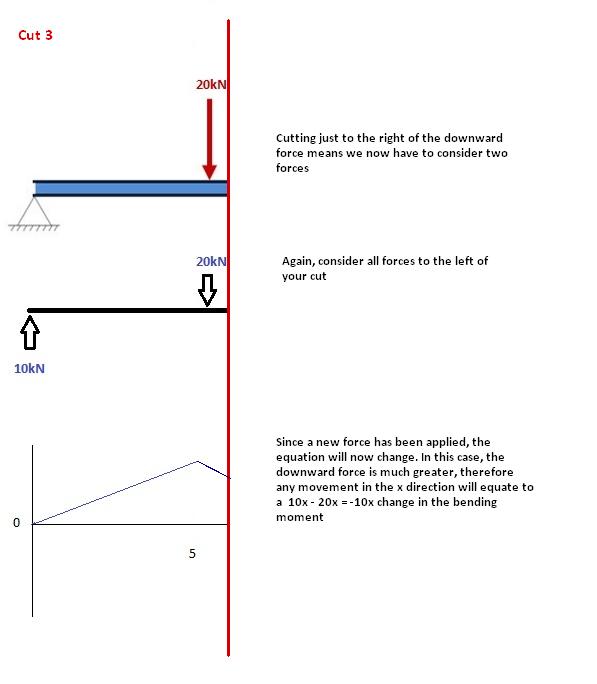
One common approach to this calculation involves four steps: step 1 is to calculate the reactions at the supports; step 2 is to imagine cutting the beam and draw a free body diagram of one of the resulting sections the beam; step 3 is to calculate the force and moment at the imaginary cut; and. step 4 is to check the calculation by doing the.
Simply Supported UDL Beam Formulas Bending Moment Equations
Bending Moment Calculator What is bending moment? Bending moment is a measure of the internal moment or torque exerted on a beam section. It quantifies the resistance of the beam to bending under an applied load. Bending moment is crucial for understanding how the beam will behave and deform under different loading conditions.
Shear force and bending moment diagram practice problem 3 YouTube

R a = R b = 1 / 2 ⋅ q ⋅ l. Those formulas can also be calculated by hand. Check out this article if you want to learn in depth how to calculate the bending moments, shear and reaction forces by hand. 2. Simply supported beam - Uniformly distributed load (UDL) at midspan (formulas) Bending moment and shear force diagram | Simply supported.
Determining Bending Stress with the Flexure Formula YouTube
In many ways, bending and torsion are pretty similar. Bending results from a couple, or a bending moment M, that is applied. Just like torsion, in pure bending there is an axis within the material where the stress and strain are zero. This is referred to as the neutral axis. And, just like torsion, the stress is no longer uniform over the cross.
Simply Supported UDL Beam Formulas Bending Moment Equations
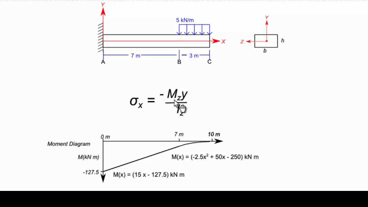
The bending moment, M, along the length of the beam can be determined from the moment diagram. The bending moment at any location along the beam can then be used to calculate the bending stress over the beam's cross section at that location. The bending moment varies over the height of the cross section according to the flexure formula below:
.